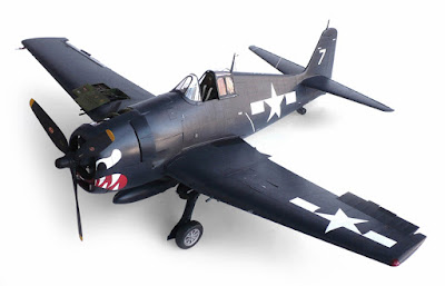
Please click on images to see them full size.
Unless otherwise indicated all photographs
©Warren Zoell

Translate

Tuesday, May 21, 2013

Dave Porter's Hawker Hurricane Diorama


Here are some images of Dave Porter's 1/48 scale Hawker Hurricane Mk1 diorama, and here in his own words is his description.
Here is a Hasegawa 1/48 scale Hurricane. It was flown by Canadian pilot William McKnight. I have depicted a typical airfield during the Battle of Britain. The figures and starter cart are from varoius sources. the aircraft was finished in Aeromaster colors.

Monday, May 20, 2013

North American RAF Mustang III


Here are some more images of Trumpeter Models 1/32 scale North American RAF Mustang III.
From Wikipedia"
In April 1942, the RAF's Air Fighting Development Unit (AFDU) tested the Mustang and found its performance inadequate at higher altitudes. As such, it was to be used to replace the Tomahawk in Army Cooperation Command squadrons, but the commanding officer was so impressed with its maneuverability and low-altitude speeds that he invited Ronnie Harker from Rolls-Royce's Flight Test establishment to fly it. Rolls-Royce engineers rapidly realized that equipping the Mustang with a Merlin 61 engine with its two-speed two-stage supercharger would substantially improve performance and started converting five aircraft as the Mustang Mk X. Apart from the engine installation, which utilized custom-built engine bearers designed by Rolls-Royce and a standard 10 ft 9 in (3.28 m) diameter, four-bladed Rotol propeller from a Spitfire Mk IX, the Mustang Mk X was a straightforward adaptation of the Mustang Mk I airframe, keeping the same radiator duct design. The Vice-Chief of the Air Staff, Air Marshal Sir Wilfrid R. Freeman, lobbied vociferously for Merlin-powered Mustangs, insisting two of the five experimental Mustang Mk Xs be handed over to Carl Spaatz for trials and evaluation by the U.S. 8th Air Force in Britain. The high-altitude performance improvement was remarkable: the Mustang Mk X (serial number AM208) reached 433 mph (697 km/h) at 22,000 ft (6,700 m), and AL975 tested at an absolute ceiling of 40,600 ft (12,400 m).
Two XP-51B prototypeswere adapted from P-51 airframes; these were a more thorough conversion than the Mustang X, with a tailor-made engine installation and a complete redesign of the radiator duct. The airframe itself was strengthened, with the fuselage and engine mount area receiving more formers because of the greater weight of the Packard V-1650-3, 1,690 lb (770 kg), compared with the Allison V-1710's 1,335 lb (606 kg). The engine cowling was completely redesigned to house the Packard Merlin, which, because of the intercooler radiator mounted on the supercharger casing, was 5 in (130 mm) taller and used an updraught induction system, rather than the downdraught carburetor of the Allison. The new engine drove a four-bladed 11 ft 2 in (3.40 m) diameter Hamilton Standard propeller that featured cuffs of hard molded rubber. To cater for the increased cooling requirements of the Merlin a new fuselage duct was designed. This housed a larger radiator, which incorporated a section for the supercharger coolant, and, forward of this and slightly lower, an oil cooler was housed in a secondary duct which drew air through the main opening and exhausted via a separate exit flap.[
It was decided that the armament of the new P-51B (NA-102) would permanently omit the previously nose-mounted machine guns used on earlier P-51 versions, and only the four wing-mounted .50 in (12.7 mm) M2/AN Browning machine guns (with 350 rpg for the inboard guns and 280 rpg for the outboard) of the P-51A would be used for its gun armament. The bomb rack/external drop tank installation, adapted from the A-36 Apache attack version, would also be used; the racks were rated to be able to carry up to 500 lb (230 kg) of ordnance and were also capable of carrying drop tanks. The weapons were aimed using an N-3B optical gunsight fitted with an A-1 head assembly which allowed it to be used as a gun or bomb sight through varying the angle of the reflector glass. Pilots were also given the option of having ring and bead sights mounted on the top engine cowling formers. This option was discontinued with the later P-51Ds.
The first XP-51B flew on 30 November 1942. Although flight tests confirmed the potential of the new fighter, with the service ceiling being raised by 10,000 feet and the top speed improving by 50 mph at 30,000 ft (9,100 m), it was soon discovered that the radiator duct airflow was breaking up at high speeds, generating a rumble as the exit shutter was closed. Testing at the Ames Aeronautical laboratory led to a redesign of the radiator scoop culminating in a forward slanted upper lip. After sustained lobbying at the highest level, American production was started in early 1943 with the P-51B (NA-102) being manufactured at Inglewood, California, and the P-51C (NA-103) at a new plant in Dallas, Texas, which was in operation by summer 1943. The RAF named these models Mustang Mk III. In performance tests, the P-51B reached 441 mph (709.70 km/h) at 30,000 ft (9,100 m). In addition, the extended range made possible by the use of drop tanks enabled the Merlin-powered Mustang to be introduced as a bomber escort with a combat radius of 750 miles using two 75 gal tanks.
The range would be further increased with the introduction of an 85 gal (322 l) self-sealing fuel tank aft of the pilot's seat, starting with the P-51B-5-NA series. When this tank was full, the center of gravity of the Mustang was moved dangerously close to the aft limit. As a result, maneuvers were restricted until the tank was down to about 25 U.S. gal (95 l) and the external tanks had been dropped. Problems with high-speed "porpoising" of the P-51Bs and P-51Cs with the fuselage tanks would lead to the replacement of the fabric-covered elevators with metal-covered surfaces and a reduction of the tailplane incidence. With the fuselage and wing tanks, plus two 75 gal drop tanks, the combat radius was now 880 miles.
Despite these modifications, the P-51Bs and P-51Cs, and the newer P-51Ds and P-51Ks, experienced low-speed handling problems that could result in an involuntary "snap-roll" under certain conditions of air speed, angle of attack, gross weight, and center of gravity. Several crash reports tell of P-51Bs and P-51Cs crashing because horizontal stabilizers were torn off during maneuvering. As a result of these problems, a modification kit consisting of a dorsal fin was manufactured. One report stated:
"Unless a dorsal fin is installed on the P-51B, P-51C and P-51D airplanes, a snap roll may result when attempting a slow roll. The horizontal stabilizer will not withstand the effects of a snap roll. To prevent recurrence, the stabilizer should be reinforced in accordance with T.O. 01-60J-18 dated 8 April 1944 and a dorsal fin should be installed. Dorsal fin kits are being made available to overseas activities"
The dorsal fin kits became available in August 1944, and were fitted to P-51Bs and P-51Cs, and to P-51Ds and P-51Ks. Also incorporated was a change to the rudder trim tabs, which would help prevent the pilot over-controlling the aircraft and creating heavy loads on the tail unit.
One of the few remaining complaints with the Merlin-powered aircraft was a poor rearward view. The canopy structure, which was the same as the Allison-engined Mustangs, was made up of flat, framed panels; the pilot gained access, or exited the cockpit by lowering the port side panel and raising the top panel to the right. The canopy could not be opened in flight and tall pilots especially, were hampered by limited headroom. In order to at least partially improve the view from the Mustang, the British had field-modified some Mustangs with clear, sliding canopies called Malcolm hoods (designed by Robert Malcolm). The new structure was a frameless plexiglas moulding which ballooned outwards at the top and sides, increasing the headroom and allowing increased visibility to the sides and rear. Because the new structure slid backwards on runners it could be slid open in flight. The aerial mast behind the canopy was replaced by a "whip" aerial which was mounted further aft and offset to the right. Most British Mk IIIs were equipped with Malcolm hoods. Several American service groups "acquired" the necessary conversion kits and some American P-51B/P-51Cs appeared with the new canopy, although the majority continued to use the original framed canopies.
P-51Bs and P-51Cs started to arrive in England in August and October 1943. The P-51B/P-51C versions were sent to 15 fighter groups that were part of the 8th and 9th Air Forces in England and the 12th and 15th in Italy (the southern part of Italy was under Allied control by late 1943). Other deployments included the China Burma India Theater (CBI).
Allied strategists quickly exploited the long-range fighter as a bomber escort. It was largely due to the P-51 that daylight bombing raids deep into German territory became possible without prohibitive bomber losses in late 1943.
A number of the P-51B and P-51C aircraft were fitted for photo reconnaissance and designated F-6C.

Friday, May 17, 2013

Kyushu J7W1 Shinden

Here are some images of Zoukei-mura's (ZM) 1/32 scale Kyushu J7W1 Shinden in Hypothetical markings.
I would argue that the Shinden would be a serious contender for the worlds most beautiful aircraft ever created.

From Wikipedia"

The Kyūshū J7W1 Shinden (震電, "Magnificent Lightning") fighter was a World War II Japanese propeller-driven aircraft prototype that was built in a canard design. The wings were attached to the tail section and stabilizers were on the front. The propeller was also in the rear, in a pusher configuration.
Developed by the Imperial Japanese Navy (IJN) as a short-range, land-based interceptor, the J7W was a response to B-29 Superfortress raids on the Japanese home islands. For interception missions, the J7W was to be armed with four forward-firing 30 mm cannons in the nose.
The Shinden was expected to be a highly maneuverable interceptor, but only two prototypes were finished before the end of war. Plans were also drawn up for a gas turbine–powered version, but this never even reached the drawing board.
The "J-" designation referred to land-based fighters of the IJN and the "-W-" to Watanabe Tekkōjo, the company that oversaw the initial design; Watanabe changed its name in 1943 to Kyūshū Hikōki K.K.
The idea of a canard-based design originated with Lieutenant Commander Masayoshi Tsuruno, of the technical staff of the IJN in early 1943. Tsuruno believed the design could easily be retrofitted with a turbojet, when suitable engines became available. His ideas were worked out by the First Naval Air Technical Arsenal (Dai-Ichi Kaigun Koku Gijitsusho), which designed three gliders designated Yokosuka MXY6, featuring canards. These were built by Chigasaki Seizo K. K. and one was later fitted with a 22 hp Semi 11 (Ha-90) 4-cylinder air-cooled engine.
The feasibility of the canard design was proven by both the powered and unpowered versions of the MYX6 by the end of 1943, and the Navy were so impressed by the flight testing, they instructed the Kyushu Aircraft Company to design a canard interceptor around Tsuruno's concept. Kyushu was chosen because both its design team and production facilities were relatively unburdened,and Tsuruno was chosen to lead a team from Dai-Ichi Kaigun Koku Gijitsusho to aid Kyushu's design works.
The construction of the first two prototypes started in earnest by June 1944, stress calculations were finished by January 1945, and the first prototype was completed in April 1945. The 2,130 hp Mitsubishi MK9D (Ha-43) radial engine and its supercharger were installed behind the cockpit and drove a six-bladed propeller via an extension shaft. Engine cooling was to be provided by long, narrow, obliquely mounted intakes on the side of the fuselage. It was this configuration that caused cooling problems while running the engine while it was still on the ground. This, together with the unavailability of some equipment parts postponed the first flight of the Shinden.
Even before the first prototype took to the air the Navy had already ordered the J7W1 into production, with quotas of 30 Shinden a month given to Kyushu's Zasshonokuma factory and 120 from Nakajima's Handa plant. It was estimated some 1,086 Shinden could be produced between April 1946 and March 1947.
On 3 August 1945, the prototype first took off, with Tsuruno at the controls, from Itazuke Air Base. Two more short flights were made, a total of 45 minutes airborne, by war's end. Flights were successful, but showed a marked torque pull to starboard (due to the powerful engine), some flutter of the propeller blades, and vibration in the extended drive shaft.

The two prototypes were the only Shinden completed. After the end of the war, one prototype was scrapped; the other J7W1 was claimed by a US Navy Technical Air Intelligence Unit in late 1945, dismantled and shipped to the United States. (Some sources claim that the USN took the first built while others state that it was the second.)
The sole remaining J7W1 was reassembled, but has never been flown in the United States; the USN transferred it to the Smithsonian Institution in 1960. It is currently in storage at the National Air and Space Museum in Washington DC.[4][10] In 1998 it was reported to be located at Building 7 of the U.S. National Air And Space Museum Garber Facility in Suitland, Maryland.


Wednesday, May 15, 2013

Dave Porter's Spitfire 12


Here are some images of Dave Porter's Spitfire 12
And here in his owns words is his description.
 Here is the new Airfix 1/48 scale Spitfire 12. Its a nice kit because you can pose all the control surfaces and it has good detail as well. I finished it in Tamaya colors and artists oils.
 

Dave Porter's DE 520

Here are some images of Dave Porter's DE 520.
And here in his own words is his description.
Here is the Tamiya De-520 in 1/48 scale. SOB. I used Aeromaster colors to
finish this one.

Monday, May 13, 2013

Voyager Probe

Here are some images of Hasegawa's 1/48 scale Voyager Probe.

From Wikipedia"
The Voyager program is an American scientific program that launched two unmanned space missions, the probes Voyager 1 and Voyager 2. These were launched in 1977 to take advantage of a favorable alignment of the planets during the late 1970s. Although they were designated officially to study just the planetary systems of Jupiter and Saturn, the space probes were able to continue their mission into the outer solar system, and they are expected to push through the heliosheath in deep space.
These two space probes were built at the Jet Propulsion Laboratory in Southern California, and they were paid for by the National Aeronautics and Space Administration (NASA), which also paid for their launchings from Cape Canaveral, Florida, their tracking, and everything else concerning the space probes.
As of April 2013, Voyager 1 is the farthest manmade object that has ever been sent from the Earth. On 15 June 2012, scientists at NASA reported that Voyager 1 might be very close to entering interstellar space and becoming the first manmade object to leave the Solar System.
Both of these scientific missions into outer space have gathered large amounts of data about the gas giants of the solar system, and their orbiting satellites, about which little had been previously known. In addition, the trajectories of the two spacecraft have been used to place limits on the existence of any hypothetical trans-Neptunian planets.
The Voyager spacecraft weighs 773 kilograms. Of this, 105 kilograms are scientific instruments. The identical Voyager spacecraft use three-axis-stabilized guidance systems that use gyroscopic and accelerometer inputs to their attitude control computers to point their high-gain antennas towards the Earth and their scientific instruments pointed towards their targets, sometimes with the help of a movable instrument platform for the smaller instruments and the electronic photography system.
The diagram at the right shows the high-gain antenna (HGA) with a 3.66 meter diameter attached to the hollow decagonal electronics container. There is also a spherical tank that contains the hydrazine monopropellant fuel.
The Voyager Golden Record is attached to one of the bus sides. The angled square panel to the right is the optical calibration target and excess heat radiator. The three radioisotope thermoelectric generators (RTGs) are mounted end-to-end on the lower boom.
Two 10-meter whip antennas, which study planetary radio astronomy and plasma waves, extend from the spacecraft's body diagonally below the magnetometer boom. The 13-meter long Astromast tri-axial boom extends diagonally downwards left and holds the two low-field magnetometers (MAG), and the high-field magnetometers remain close to the main antenna.
The instrument boom extending upwards holds, from bottom to top: the cosmic ray subsystem (CRS) left, and Low-Energy Charged Particle (LECP) detector right; the Plasma Spectrometer (PLS) right; and the scan platform that rotates about a vertical axis.
The scan platform comprises: the Infrared Interferometer Spectrometer (IRIS) (largest camera at top right); the Ultraviolet Spectrometer (UVS) just above the UVS; the two Imaging Science Subsystem (ISS) vidicon cameras to the left of the UVS; and the Photopolarimeter System (PPS) under the ISS.
Only five investigation teams are still supported, though data is collected for two additional instruments. The Flight Data Subsystem (FDS) and a single eight-track digital tape recorder (DTR) provide the data handling functions.
The FDS configures each instrument and controls instrument operations. It also collects engineering and science data and formats the data for transmission. The DTR is used to record high-rate Plasma Wave Subsystem (PWS) data. The data is played back every six months.
The Imaging Science Subsystem, made up of a wide angle and a narrow angle camera, is a modified version of the slow scan vidicon camera designs that were used in the earlier Mariner flights. The Imaging Science Subsystem consists of two television-type cameras, each with eight filters in a commandable Filter Wheel mounted in front of the vidicons. One has a low resolution 200 millimeter wide-angle lens with an aperture of f/3 (the wide angle camera), while the other uses a higher resolution 1.500 meter narrow-angle f/8.5 lens (the narrow angle camera).

Saturday, May 11, 2013

The U.S.S. Enterprise Exploration Set

Here are some images of AMT's 1/1.35 scale(?) U.S.S. Enterprise Exploration Set from Star Trek the original series.
Ah to be a kid again!
Back in the mid 1970's if you were an 8 to 11 year old kid the Exploration Set was a must have. Many of us kids back in those days did have and had built this kit, and man did we use them. All sorts of adventures.
Now of course upon opening this kit today, the first thing one notices is the size. They're so small.
Back when I was a kid the Tricorder, Phaser and Communicator all looked life size. LOL!
One tends to forget that sort of thing after 35 years of not seeing the kit.
Another obvious thing I noticed is the lack of accuracy. They look as though they were designed by a drunken gorilla with a slide rule and coke bottle glasses.
But as kids if one were to tell us the inaccuracy of this kit, we wouldn't have cared. It was Star Trek man!
Looking at it today regarding accuracy I still don't care. It was part of our childhood, mine included.
I've been led to understand that Round 2 models will be re releasing this kit again in the near future.
This time with upgrades and photo etch parts. I suspect there will have to do some new tooling as well.
But hey! All I can say is that it was sure great to be able to track down one of these old kits.
I realize this kit unbuilt has a collectors value but I don't care. It was sure great to relive a small part of my childhood again building this.
Ah memories!

Thursday, May 9, 2013

Type 039 Song Class attack submarine

Here are some more images of Bronco Models 1/200 scale Type 039 Song Class attack submarine.

From Wikipedia"

The Type 039 submarine (NATO code name Song class) is a class of diesel-electric submarines of the People's Liberation Army Navy. The class is the first to be fully developed within China and also the first Chinese submarine to use the modern teardrop hull shape.
The People's Republic of China's first submarine design was the locally-produced derivative of the Romeo class submarines provided to China by the Soviet Union. Large numbers of these were built, but their obsolete design, derived from World War II submarine technology, led China to develop a wholly new class on its own, resulting in the Type 039.
Designed for attacking both other submarines and surface ships with torpedoes, the submarine uses a modern teardrop-shape hull for underwater performance. The hull incorporates four rudders and is propelled by a single propeller. For quieter operation, the engine was mounted with shock absorbers and the hull is plated in rubber tiles for sound deadening. Development was not without problems, as a lengthy testing period for the first vessel (320) attests. Problems with noise levels and underwater performance led to revisions in the design and only a single boat was ever built to the original specification.
Improvements led to the specification for the Type 039G, which became the bulk of production, with seven of the type entering service. Elimination of the stepped design for the conning tower is the primary visual cue for identification of the G variant.
This class has three versions: the original Type 039, Type 039G and Type 039A. The most obvious visual difference between the three types is the conning tower. The Type 039's conning tower is stepped, rising aft. In an effort to shrink the submarine's acoustic signature, the Type 039G's conning tower was given a more conventional shape. The Type 039A also has a conning tower of more conventional shape, but the tower lacks the diving planes present on the conning towers of both the Type 039 and the Type 039G.
Primary weapon for the Type 039 is the 533 mm Yu-4 torpedo, a locally produced passive homing 40-knot (74 km/h) torpedo based on the SAET-50 and roughly comparable to the SAET-60. Surface targets may be attacked at up to 15 km. Yu-6 wire-guided torpedoes may also be used for targeting submarines. It is also likely that the Type 039 is capable of carrying the YJ-8 anti-ship missile, a cruise missile which can be launched from the same tube as the boat's torpedoes, and can target surface vessels at up to 80 km. The missile is subsonic and carries a 165 kg warhead. For mining operations, in place of torpedoes, the submarine can carry 24 to 36 naval mines, deliverable through the torpedo tubes. The general designer of the torpedo and missile launching system is Mr. Sun Zhuguo (孙柱国, 1937-), and the launching system is compatible with AShM, ASW, torpedoes of both China and Russian/Soviet origin.
Although Type 039 has successfully test fired the CY-1 ASW Missile under water like the Yuan-class submarine, the status of the missile is in question because nothing is heard about it entering mass production. The CY-1 ASW missile has a maximum range of 18 km (10 nm), and when using A244 or Mark 46 torpedo as a payload.

Wednesday, May 8, 2013

U-Boot Typ 212 A

Here are some more images of Revell's 1/144 scale type 212 A U Boat.
What can I say but this model was fun to build. Not much to it but a nice result in the end.

From Wikipedia"

The German Type 212 class, also Italian Todaro class, is a highly advanced design of non-nuclear submarine (U-boat) developed by Howaldtswerke-Deutsche Werft AG (HDW) and Fincantieri S.p.a. for the German and Italian Navy. It features diesel propulsion and an additional air-independent propulsion (AIP) system using Siemens proton exchange membrane (PEM) hydrogen fuel cells. The submarine can operate at high speed on diesel power or switch to the AIP system for silent slow cruising, staying submerged for up to three weeks without surfacing and with no exhaust heat. The system is also said to be vibration-free, extremely quiet and virtually undetectable.
Type 212 is the first of the only two fuel cell propulsion system equipped submarines ready for series production by 2007, the other being the Project 677 Lada class submarine designed by Russian Rubin Design Bureau.
At the beginning of the 1990s the German Navy was seeking a replacement for the Type 206 submarines. Initial study started on a Type 209 improved design, with AIP capability, called Type 212.
The final programme started in 1994 as the two navies of Germany and Italy began working together to design a new conventional submarine, respectively to operate in the shallow and confined waters of the Baltic sea and in the deeper waters of the Mediterranean sea. The two different requirements were mixed into a common one and, because of significant updates to the design, the designation was changed to Type 212A since then.
In 1996 a Memorandum of Understanding (MOU) gave the start to the cooperation. Its main aim was the construction of identical boats and the start of a collaboration in logistic and life-cycle support for the two navies.
The German government placed an initial order of four Type 212A submarines in 1998. The German Submarine Consortium built them at the shipyards of HDW and Thyssen Nordseewerke GmbH (TNSW) of Emden. Different sections of the submarines were constructed at both sites at the same time and then half of them were shipped to the respective other yard so that both HDW and Thyssen Nordseewerke assembled two complete submarines each.
In the same year the Italian government placed an order of two U212A submarines built by Fincantieri for the Marina Militare (Italian Navy) at Muggiano shipyard, designated as the Todaro class.
The German Navy ordered two additional, improved submarines in 2006, to be delivered from 2012 on. They will be 1.2 meters longer to give additional space for a new reconnaissance mast.
On 21 April 2008 the Italian Navy ordered a second batch of submarine in the same configuration of the original ones. Some upgrading should involve materials and components of commercial derivation, as well as the software package of the CMS. The intention is to keep the same configuration of the first series and reduce maintenance costs.
The export-oriented Type 214 submarine succeeds the Type 209 submarine and shares certain features with the Type 212A, such as the AIP fuel cell propulsion.
Partly owing to the "X" arrangement of the stern planes, the Type 212 is capable of operating in as little as 17 metres of water, allowing it to come much closer to shore than most contemporary submarines. This gives it an advantage in covert operations, as SCUBA-equipped commandos operating from the boat can surface close to the beach and execute their mission more quickly and with less effort.
A notable design feature is the prismatic hull cross-section and smoothly faired transitions from the hull to the sail, improving the boat's stealth characteristics. The ship and internal fixtures are constructed of nonmagnetic materials, significantly reducing the chances of it being detected by magnetometers or setting off magnetic naval mines.
The low emission profile allowed the submarines in exercises to intrude even into well protected opposing forces such as carrier formations with their screen.
Although hydrogen–oxygen propulsion had been considered for submarines as early as World War I, the concept was not very successful until recently due to fire and explosion concerns. In the Type 212 this has been countered by storing the fuel and oxidizer in tanks outside the crew space, between the pressure hull and outer light hull. The gases are piped through the pressure hull to the fuel cells as needed to generate electricity, but at any given time there is only a very small amount of gas present in the crew space.
Currently, the Type 212A is capable of launching the fiber optic-guided DM2A4 Seehecht ("Seahake") heavyweight torpedoes, the WASS A184 Mod.3 torpedoes, the WASS BlackShark torpedoes and short-range missiles from its six torpedo tubes, which use a water ram expulsion system. Future capability may include tube-launched cruise missiles.
The short-range missile IDAS (based on the IRIS-T missile), primarily intended for use against air threats as well as small or medium-sized sea- or near land targets, is currently being developed by Diehl BGT Defence to be fired from Type 212's torpedo tubes. IDAS is fiber-optic guided and has a range of approx. 20 km. Four missiles fit in one torpedo tube, stored in a magazine. First deliveries of IDAS for the German Navy are scheduled from 2014 on.
A 30 mm auto-cannon called Muräne (moray) to support diver operations or to give warning shots is being considered too. The cannon, probably a version of the RMK30 built by Rheinmetall, will be stored in a retractable mast and can be fired without the boat emerging. The mast will also be designed to contain three Aladin UAVs for reconnaissance missions. This mast is likely to be mounted on the 2nd batch of Type 212 submarines for the German Navy.

Tuesday, May 7, 2013

Cadaques Fishing Boat

Here are some more images of Artesania Latina's 1/20 scale Cadaques Fishing Boat. The Cadeques is a traditional fishing boat seen throughout the northern stretch of the Costa Brava and the Rosellon coastline in the south of France. This model makes a great entry level kit if one wishes to get into wooden ship building.

Monday, May 6, 2013

King Of The Mississippi

Here are some more images plus a composite of Artesania Latinas 1/80 scale paddle sternwheeler  riverboat steamer King of the Mississippi.

From Wikipedia"
  paddle steamer is a steamship or riverboat powered by a steam engine that drives paddle wheels to propel the craft through the water. In antiquity, Paddle wheelers followed the development of poles, oars and sails, where the first uses were wheelers driven by animals or humans. Modern paddle wheelers may be powered by diesel engines. Save for tourism and small pleasure boats (paddle boats), paddle propulsion is largely superseded by the screw propeller and other marine propulsion that have a higher efficiency, especially in rough or open water.
 The paddle wheel is a large steel framework wheel. The outer edge of the wheel is fitted with numerous, regularly-spaced paddle blades (called floats or buckets). The bottom quarter or so of the wheel travels underwater. An engine rotates the paddle wheel in the water to produce thrust, forward or backward as required. More advanced paddle wheel designs feature feathering methods that keep each paddle blade closer to vertical while in the water to increase efficiency. The upper part of a paddle wheel is normally enclosed in a paddlebox to minimise splashing.

There are two basic ways to mount paddle wheels on a ship; either a single wheel on the rear, known as a stern-wheeler, or a paddle wheel on each side, known as a side-wheeler.
Both sternwheelers and sidewheelers were used as riverboats in the United States. Some still operate for tourists, for example on the Mississippi River.
Side-wheelers are used as riverboats and as coastal craft. Though the side wheels and enclosing sponsons make them wider than stern-wheelers, they are more maneuverable, since they can usually move the paddles at different speeds, and even in opposite directions. This extra maneuverability makes side-wheelers popular on the narrower, winding rivers of the Murray-Darling system in Australia, where a number still operate.
European side-wheelers, such as the PS Waverley, connect the wheels with solid drive shafts that limit maneuverability and give the craft a wide turning radius. Some were built with paddle clutches that disengage one or both paddles so they can turn independently. However, early experience with side-wheelers required that they be operated with clutches out, or as solid shaft vessels. Crews noticed that as ships approached the dock, passengers moved to the side of the ship ready to disembark. The shift in weight, added to independent movements of the paddles, could lead to imbalance and potential capsizing. Paddle tugs were frequently operated with clutches in, as the lack of passengers aboard meant that independent paddle movement could be used safely and the added maneuverability exploited to the full.


Sunday, May 5, 2013

K7 Space Station


Here are some more images of AMT's K7 Space Station from Star Trek TOS from the episode The Trouble with Tribbles. From Wikipedia "Deep Space Station K7 was based on a model for a real-life space station/moon base proposed by Douglas Aircraft as early as 1960. Intended to be housed in the top stage of the Saturn IB or Saturn V rocket, it was designed to deploy like an inflatable balloon. This space station was also available as a model from Aluminium Metal Toys.

On stardate 4523.3, Captain James T. Kirk and his crew are called to Deep Space Station K7 by a priority-one distress call. The station is near Sherman's Planet, a world in a sector of space disputed between the Federation and the Klingon Empire. Under the terms of the Organian Peace Treaty, Sherman's Planet would be awarded to whichever side demonstrates that it can manage it more efficiently.
Kirk is furious when he later realizes the distress call was unwarranted, and the undersecretary in charge of agriculture in the sector, Nilz Baris, simply wants someone to guard the shipments of quadrotriticale, a four-lobed wheat-rye hybrid grain, bound for Sherman's Planet. To Baris's annoyance, Kirk assigns two token guards to the task shortly before learning that Starfleet Command endorses Baris's concerns. A Klingon ship soon arrives at the space station and requests that its crew be granted shore leave, as entitled under the treaty. Kirk tells the Klingon captain Koloth that he may only bring members of his crew down 12 at a time, and that he will provide one security guard for each Klingon who beams down.
Meanwhile, an independent trader, Cyrano Jones, brings some little furry animals called tribbles onto the station to sell; he gives one to Uhura as a marketing ploy. She brings it on board the Enterprise, where it and its offspring are treated as adorable pets. The animals purr a relaxing trill that the crew (even the stoic Mr. Spock) find soothing. Klingons, however, find tribbles very annoying, and the feeling is mutual: tribbles emit an ear-piercing shriek of aggression, and jump, whenever they are near Klingons. (It has subsequently been explained that tribbles have a keen sense of smell and find food by scent, that they find the smell of Klingons offensive, and that Klingons, who are likewise spoken of as having a keen sense of smell, find the "stench" of tribbles repulsive.)
The "trouble" with the tribbles is that they reproduce far too quickly and are capable of eating a planet barren if their breeding is not controlled; in the words of Dr. McCoy, "they are born pregnant" and threaten to consume all the onboard supplies. The problem is aggravated when it is discovered that the creatures are entering essential ship systems, interfering with their functions and consuming any edible contents present. Kirk realizes that if the tribbles are getting into the Enterprise's stores, then they are a direct threat to the grain stores aboard the station. However, upon examining the holds, Kirk learns that it is already too late; the tribbles have indeed eaten the grain—a fact he learns the hard way, by being buried to more than half his own height in tribbles when he opens a hold with an overhead hatch. It appears the mission has ended in a fiasco. On top of that, Koloth wants a formal apology from Kirk, since some of the Enterprise crew members have started, though not without provocation, a western-style brawl with the Klingon crew in the station's bar.
Spock and McCoy, however, soon discover that around half the tribbles in the hold are dead and many of the rest are dying, alerting the Federation that the grain has been poisoned. Furthermore, the tribbles also give away the identity of a surgically altered Klingon agent responsible. The saboteur is the only "human" the tribbles do not like: Arne Darvin, Baris's own assistant. He had infected the grain with a virus that becomes an inert material in an organism's bloodstream; the more that is eaten, the more inert matter builds up, till the organism cannot take in enough nourishment to survive and essentially starves to death. Upon a medical scan by Dr. McCoy, it is revealed that Darvin is indeed a Klingon in disguise. Thus the tribbles redeem themselves and enable the Federation to score a diplomatic victory against the Klingons. As for Cyrano Jones, who introduced the species to the station, he is ordered to remove the tribbles from the station (a clean-up task that Spock estimates will take 17.9 years) or be imprisoned for 20 years for transporting a dangerous life form off its native planet.
Just before the Klingon departure, all tribbles that were on the Enterprise are somehow beamed onto the Klingon ship by Scotty as a retaliation for the troubles the Klingons have caused, where, in his words, "they'll be no tribble at all."

Chinese Junk Red Dragon


Here are some more images of Artesania Latinas 1/60 scale Chinese Junk Red Dragon. These ships plied the rivers and oceans of the far east from Singapore up the northern China.Ships like this had such a sturdy and tough workhorse like design that even to this day there are still similar examples in use. The woods used for this model were Sapelly, African Walnut, Boxwood, Applewood and of coarse Plywood.

From Wikipedia"
A junk is an ancient Chinese sailing vessel design still in use today. Junks were developed during the Han Dynasty (206 BC–220 AD) and were used as sea-going vessels as early as the 2nd century AD. They evolved in the later dynasties, and were used throughout Asia for extensive ocean voyages. They were found, and in lesser numbers are still found, throughout South-East Asia and India, but primarily in China, perhaps most famously in Hong Kong. Found more broadly today is a growing number of modern recreational junk-rigged sailboats.
Junks were efficient and sturdy ships that sailed long distances as early as the 2nd century AD. They incorporated numerous technical advances in sail plan and hull designs that were later adopted in Western shipbuilding.
The historian H. Warington Smyth considered the junk one of the most efficient ship designs, stating that "As an engine for carrying man and his commerce upon the high and stormy seas as well as on the vast inland waterways, it is doubtful if any class of vessel… is more suited or better adapted to its purpose than the Chinese or Indian junk, and it is certain that for flatness of sail and handiness, the Chinese rig is unsurpassed."